The 4S4P modular architecture is constructed from sixteen standard 100Ah cells, delivering 20.48kWh of energy; it offers exceptional flexibility, enabling compatibility with any inverter topology while supporting on-demand expansion.
Configuration cheat sheet
Starting from a single 12.8V 100Ah unit, here is how series and parallel combinations scale. Use this table to match the configuration to your project's voltage and runtime requirements.
|
Config |
Voltage |
Capacity |
Energy |
Best for |
|
1S1P |
12.8V |
100Ah |
1.28kWh |
Small 12V loads, RV aux |
|
4S1P |
51.2V |
100Ah |
5.12kWh |
48V inverter, compact solar |
|
1S4P |
12.8V |
400Ah |
5.12kWh |
12V high-draw, marine |
|
4S4P |
51.2V |
400Ah |
20.48kWh |
Commercial ESS, off-grid |
Why choose the 4S4P architecture?
Distributed fault tolerance
With sixteen independent units, a single cell fault or BMS trip isolates one battery — not the entire bank. Maintenance and swap-out happen at the unit level without system downtime.
48V inverter compatibility
The 4S output of 51.2V sits precisely in the operating window of all major 48V-class off-grid inverters. No step-up converter needed, which eliminates conversion losses and reduces the complexity of the bill of materials (BOM).
Modular expansion
Projects that begin at 5.12kWh (4S1P) can double or quadruple capacity by adding parallel strings on-site — without rewiring the inverter or replacing any existing hardware.
Standardized procurement
A single SKU — the 12.8V 100Ah unit — covers every project scale from 1.28kWh to 20.48kWh.
Essential checks before project commissioning
These are the most common failure points in field deployments. Address each before energizing the bank.
BMS high-voltage rating. Standard 12V BMS MOSFETs break down above 30–40V. In a 4S string, full pack voltage (51.2V) appears across each switch during a fault disconnect. Use only batteries with a BMS rated for series-stack operation — our units carry a ≥60V Vds MOSFET array specifically for this. Never mix BMS firmware versions across a series string.
Voltage balance before parallel connection. Measure open-circuit voltage on every unit before closing the parallel bus. Any two batteries with more than 0.1V difference will create an instantaneous high-current equalizing surge at the moment of connection — this can weld contactors, destroy terminal lugs, and trip BMS protection simultaneously across multiple units. Charge to match first.
Same brand, model, and production batch. Internal resistance divergence between batches causes unequal load sharing. The fastest-aging cell in a string sets the ceiling for the entire bank's usable capacity. Specify batch-matched units in your purchase orders.
Equal-length interconnect cables. In a parallel bank, resistance asymmetry in cabling creates current imbalance. Use identical cable lengths and cross-sections between each battery and the busbar. Even a 15cm difference matters at 200A+.
Individual fusing per unit. Each battery's positive terminal should have its own fuse or breaker before reaching the bus. This allows safe isolation of a single unit without de-energizing the full bank during maintenance.
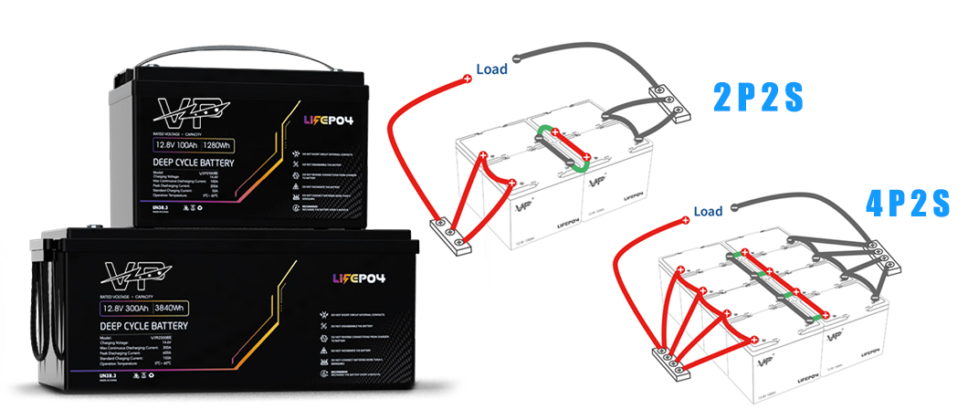
Connection Strategy for Large Battery Packs
Diagonal wiring method — 4P parallel bank
Using a diagonal wiring method, the current is forced to flow in opposite directions along the full length of the two busbars; this makes the impedance path of each cell more consistent, thus ensuring that the current is evenly distributed among all four cells.
For systems with a continuous current exceeding 200A, solid copper busbars or plated busbars should be used instead of single cables at parallel connection points. The busbar eliminates the imbalance caused by impedance differences when multiple cables are connected in parallel and provides a stable mechanical fixing point for the terminal blocks of each battery. When determining the cross-sectional area of the busbar, ensure that the temperature rise does not exceed 30°C under the maximum rated current—specific calculations should refer to the standard current carrying capacity table for the busbar material and ambient temperature.
In a 4S4P (4 series 4 parallel) configuration, four parallel groups should be built first (i.e., the single cell is expanded from 1P to 4P at each series position), the voltage balance between the groups should be confirmed, and then the series connection should be performed. This operational sequence can prevent accidental short circuits caused by inconsistent battery voltages during assembly.
Beyond 4S4P: MW-scale and complex integrated applications
Customized energy storage systems (ESS)
When project requirements exceed what a 4S4P bank can deliver, our engineering team designs purpose-built systems around your load profile and site constraints.
Our technical capabilities include: rack-mounted high-voltage energy storage cabinets; support for CAN bus and RS485 protocol integration to adapt to third-party battery management systems (BMS) and inverters; and factory-pre-wired components that can reduce on-site commissioning time from several days to several hours.
Planning a storage project?
Our engineering team provides wiring schematics, configuration specifications, and commissioning checklists tailored to your project's voltage, capacity, and inverter requirements — at no cost for qualified integrators and distributors.